专业的物联网传感器
与解决方案供应商
- 首页
-
产品中心
 激光粉尘传感器>
 红外二氧化碳传感器>
 红外甲烷传感器>
 红外一氧化碳传感器>
 红外二氧化硫传感器>
 红外六氟化硫传感器>
 极普/荧光法溶氧电极>
 PVC膜电极>
 晶体膜电极>
 一氧化碳报警器>
 家居环境检测仪>
 土壤养分/重金属检测仪>
 农药残留检测仪>
 红外二氧化氮传感器>
 红外一氧化氮传感器>
 红外碳氢传感器>
 网络继电器>
 串口服务器>
 网关>
网关>
 贯桥云盒>
贯桥云盒>
 网络字符叠加器>
 土壤速测平台>
 土壤速测仪>
 食品添加剂/调味品/色素>
 壁挂式传感器>
 土壤类传感器>
 溶解氧传感器>
 扬尘监测系统>
 机房环境监控>
 公厕类传感器>
 便携式气体检测仪>
 PID原理VOC传感器>
 国标法水质在线分析仪>
 一氧化氮/二氧化氮/二氧化硫>
 MEMS数字量气体传感器>
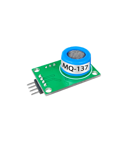
 半导体气体传感器>
 MEMS模拟量气体传感器>
 有毒有害物质/真菌霉素类>
 TO封装传感器>
 液位芯片>
液位芯片>
 防爆式传感器>
 JEC-4系列电化学传感器>
 紫外吸收法臭氧传感器>
 气象/环境类传感器>
 水质PH传感器>
 VOCs在线监测系统>
 市政类传感器>
 水质测定/消解仪>
 油烟检测仪>
 氧气/臭氧/一氧化碳/乙醇>
 工业气体报警器>
 重金属含量/食用油检测>
 数字温度传感器芯片>
 分体式传感器>
 JEC-7系列电化学传感器>
 农业控制系统>
 水质电导率传感器>
 油烟在线监测系统>
 压力/微压差传感器>
 路灯/亮化控制器>
 水质速测平台>
 负氧离子检测仪>
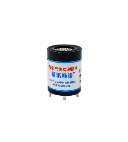
 可燃气体/甲烷模组>
 DOAS传感器>
 抗生素残留类/瘦肉精激素农药残留/病害肉诊断>
 非接触式测温探头>
 风管式传感器>
 科研/AI仪器类>
 浊度/悬浮物/污泥浓度传感器>
 大气微观站>
 液位传感器>
 电梯监控系统>
 便携式气象站>
 溶氧仪>
溶氧仪>
 硫化氢/氯化氢/氰化氢/磷化氢>
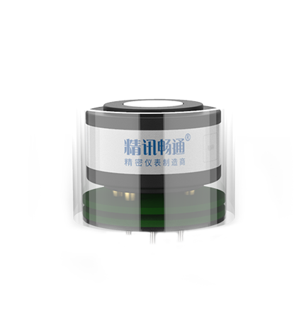
 固态电解质气体传感器>
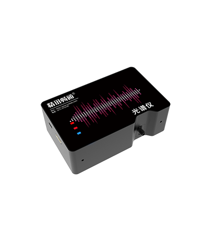 光谱仪>
光谱仪>
 水产品安全类>
 红外热释电传感器>
 液晶大屏传感器>
 灌溉类设备>
 COD/BOD/叶绿素/蓝绿藻/荧光剂传感器>
 氮氧化物在线监测系统>
 电流/电压/断电传感器>
 满意度调查机>
 水质离子计>
 便携式检漏仪>
 氢气/氨气/氯气/氟气/氡气>
 水酒饮品分析>
 MEMS气体流量传感器>
 荧光法氧气传感器>
 铝合金壳体传感器>
 塔机安全监测系统>
 加速度/振动/温度传感器>
 地质类传感器>
 数采仪>
数采仪>
 氟利昂/环氧乙烷/苯/过氧化氢>
 电磁阀>
电磁阀>
 烟气在线监测系统>
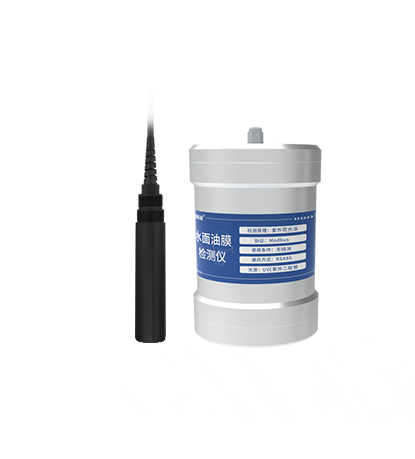 水中油/水面油膜检测仪>
 泵吸式气体检测仪>
 化学类药物>
 温度传感器>
 百叶箱式传感器>
 固态电解质气体模组>
 畜牧养殖>
畜牧养殖>
 水质离子类传感器>
 工业测温传感器>
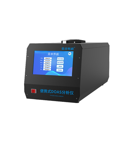 便携式DOAS气体检测仪>
 动物疫病检测仪>
 积水类传感器>
 智能显示仪表盒>
 家用/园林灌溉控制器>
 便携式COD/重金属消解仪检测仪>
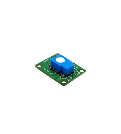
 半导体气体传感器模组>
 过滤器>
过滤器>
 九项水质检测仪>
 JEC7系列气体传感器模组>
 水质余氯传感器>
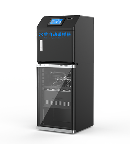 水质自动采样器>
水质全光谱检测仪>
- 解决方案
- 技术支持
- 关于精讯
- 新闻中心
- 人才发展